Design and Experimentation of a 1 MW Horizontal Axis Wind Turbine ()
1. Introduction
The horizontal axis wind turbine is the most efficient and most developed for electricity generation on large scale. Research focuses primarily on reducing the size of the turbine to achieve lower production and installation costs [1-7], however, the new design trends in order of importance are increasing efficiency, increasing resistance to dynamic loads, mass reduction and reduction of acoustic noise emission. In general, there are many parameters that influence a good design of wind turbines [8,9]. Among the main parameters are the rated wind speed, the tip speed and solidity. The efficiency of the wind turbine is function of tip speed ratio defined by the ratio of tangential velocity at rotor tip and atmospheric wind speed. The turbines with tip speeds greater than three are useful for the production of electricity. The designs widely used for power generation on a large scale are Darrieus rotors and horizontal axis rotors of three or two blades. In order to
maximize the wind resource and minimize production costs and installation costs, improved designs have emerged to multiply the power per unit from two to ten times the power generated by a three-blade rotor, while these systems have some disadvantages with respect to traditional systems. The diffuser system shown in Figure 1 has enabled an energy advantage from two to three times that the conventional system is a silent machine, and blades do not require sophisticated airfoil sections. Currently, the only disadvantage of this system is its scaling to over 1 MW powers.
Dual rotor systems or multiple rotors provide better aerodynamic performance than Betz limit. For a dual rotor rotating in the opposite direction in Figure 2(a), the power captured by each rotor is summed in the rigid shaft to give a maximum theoretical yield of 69%.
For systems with multiple rotors rotating in the same direction and subject to an flexible shaft can be achieved
 (a)
(a) (b)
(b)
Figure 1. Wind turbines with diffuser system. (a) Wind Lens; (b) FloDesign.
 (a)
(a) (b)
(b) (c)
(c)
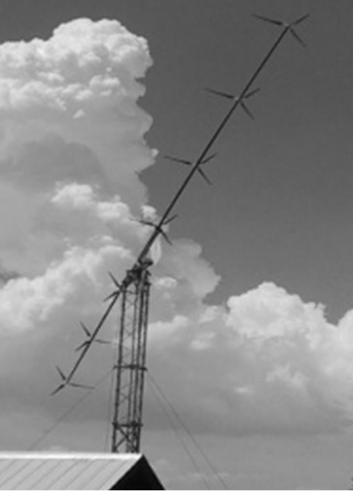
Figure 2. Unconventional designs. (a) Double rotor; (b) Multiple rotors; (c) Multiple rotors with flexible shaft (Selsam).
ten times the power of a conventional horizontal axis wind turbine in Figures 2(b) and (c). This energy advantage is achieved because the flexible shaft allows carrying the rotors to free flow zones with higher energy density than the flow behind the upstream rotor. The main disadvantage of these systems is the generation of noise and the scaling to multimegawatts power, and its main use is for residential application.
The horizontal axis wind turbine with three blades is applied to generation of large-scale electric power, and the power range is from several tens of Watts until multimegawatt machines.
2. Wind Turbine Aerodynamics
Figure 3 shows the force and speed diagram of a blade element. The rotor is driven by an air stream velocity U∞ and rotates at speed ω. The differential element blade moves with a tangential velocity ωr. The sum of the wind velocity and the tangential velocity produces a relative velocity Vr. This flow produces a resultant force composed of a lift force normal to the relative velocity and a drag force in the direction of the relative velocity. The component of the lift force on the rotation plane of the rotor is the force which causes rotation of the turbine, in the opposite manner; the drag force opposes the rotation and represents loss energy.
The yield depends on rotor speed. The relation that

Figure 3. Diagrams of speeds and forces in a blade element [12].
determines the speed of one turbine is the tip speed ratio (TSR). The TSR is the ratio between tangential velocity and free stream velocity, Equation (1).
 (1)
(1)
The main parameters which dominate the behavior of torque and efficiency curves for each configuration are the number of rotor blades, radial distribution of the chord, airfoil aerodynamic characteristics and twist angle distribution. From the energy and structural point of view, the flow behavior behind the rotor is important in the operation. High pressure gradients in the wake produce vibration and efficiency losses. The contribution of power in the blade increases in the radial direction. But in the region near the tip, the power coefficient decreases due to vortex generation. This phenomenon can be significantly reduced by modifying the tip shape [10,11].
3. Methodology
The process followed for the design and analysis of 1 MW wind turbine are shown in Figure 4. The process begins with the introduction of the design parameters to the computer program developed in MATLAB® called VDTURBINE. This program was built to solve the design equations that will be shown in the next section of this paper. The design parameters that were introduce in
the program are rated power, aerodynamic performance that we propose, the free stream velocity, air density and the airfoil type. The program has an interface with Xfoil and then gets the values of lift and drag coefficient according to the angle and chord length in each radial section of the blade. These values are necessary for the design and for calculation of power coefficient.
When the computer program obtains the preliminary geometry, this is linearized to reduce the blade surface and thereby reduce the material used for its construction. Linearized geometry is then subjected to two processes of analysis, one numeric and other experimental. For experimental analysis VDTURBINE program develops the power coefficient calculation for the conditions that we indicate.
For this case we will carry out a comparison of the wind rotor performance when taking into account certain correction factors into a model of ideal flow. Then we propose three cases, the first is a calculation of the power coefficient excluding any correction factor to the equation of ideal flow. In the second case we take into account only the tip loss factor and in the third case the tip loss factor and drag are taken into account.
In the experimental part, the design linearized was scaled for the development of experimental tests in an axial flow fan of 80 cm in diameter. Scaling design is constructed of fiberglass and polyester resin with a diameter equal to the fan. Then the rotor is attached to an electric generator to extract the power of the turbine when placed in front of the airflow. From the readings of voltage and electric current in the electric generator and reading the wind speed are calculated power coefficients for different rotor tip speed ratios. Finally, a comparison of numerical results with experimental test was done to determine the accuracy of the numerical calculations with respect to the experimental results for different flow conditions.
4. Wind Turbine Design
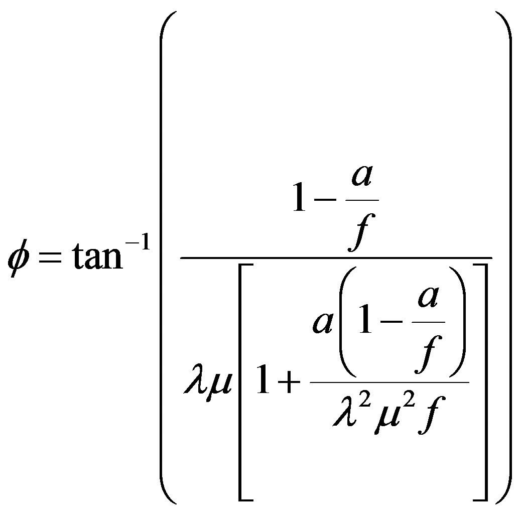
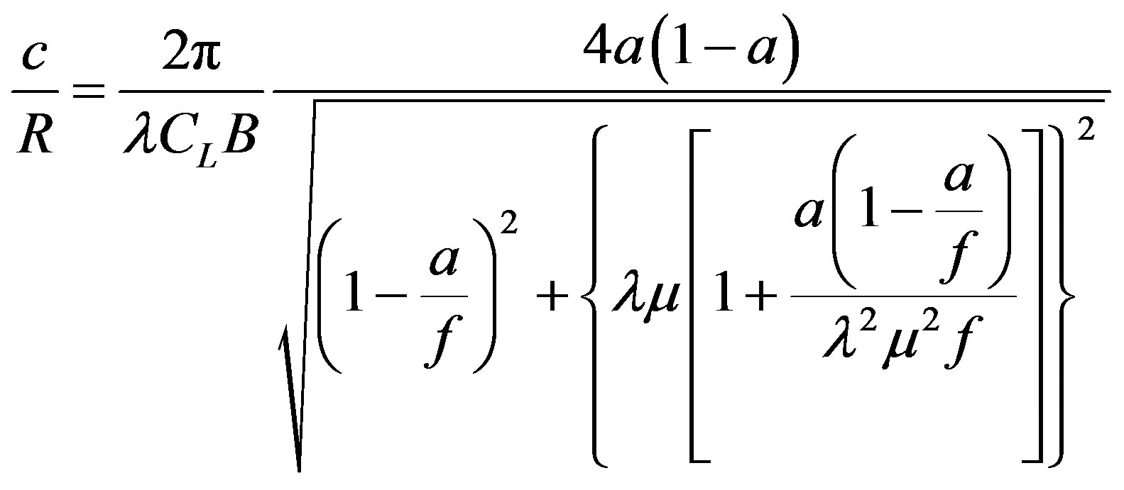
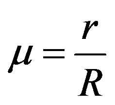
This paper develops the design of a 1 MW wind turbine power, using Blade Element Theory (BET) and Momentum (BEM) at each blade element. The procedure develops a preliminary design of the turbine blades by solving Equations (2)-(7) for each differential blade elements in each radial position.
 (2)
(2)
 (3)
(3)
 (4)
(4)
where
 (5)
(5)
 (6)
(6)
 (7)
(7)
The solution of the equations above is shown in Figure 5, for a TSR of 8 and a wind speed of 8 m/s to achieve their rated power of 1 MW. The resulting geometry is given for the ideal condition by Equations (2) and (4) and considering losses on the blades tip.
The performance of the geometry shown in Figure 5 is evaluated by the equations resulting from the combined model blade element theory in one dimension and a momentum analysis in each blade element, known as strip theory, Equations (8) and (9). These equations contain tip loss factor and drag coefficient for better approximation of turbine performance.
 (8)
(8)
 (9)
(9)
 (10)
(10)
 (11)
(11)
Equations (10) and (11) are used to calculate the axial induction factor when the value calculated by Equation (8) is greater than 0.4 or when the thrust coefficient is bigger than 0.96f [12]. The solution of Equations (8) and (9) is an iterative process. Loop ends when the desire accuracy is achieved in induction factors and the procedure is applied for each blade element. Once the induction factors are calculated, power coefficient is found from equation below, Equation (12). For the calculation propose was made a computational program named VDTURBINE to solve the aerodynamics design and calculation of the wind rotor.
 (12)
(12)
Some important results are shown in the figures below. The yield is plotted against radio ratio. Power contribution near the root region is poor. This is increased proportionally towards tip and it changes near the tip where the power coefficient changes in direction decreasing its magnitude, Figure 6.
In a practical design, root geometry is not enough important because the power contribution is smaller than in the tip. However the most important power contribution is in the region near the tip, about 70% to 90% of radial distance.
5. Linearized Design
The resulting geometry with BEM design was modified to reduce the size of the chord near the blade root and
thus reduce the production costs in real scale. This was accomplished considering the section of the blades where the contribution of power reaches between 60% and 80% of the nominal power.
The new geometry of the blades is calculated linearizing the chord of Figure 5 between 70% and 90% of the radial length, where power contribution is near 80% of total power. Equation (13) shows the expression resulting from the linearization.
 (13a)
(13a)
 (13b)
(13b)
Linearized geometry with Equations (13a) and (13b) and the yield is shown in Figure 7. Area reduction in the linearized geometry is approximately one third, Figure 7(a). The performance of the new geometry had a small reduction and this sacrifice reduce the production costs in the turbine (Figure 7(b)).
The final design parameters are shown in Table 1. The design is performed for a fixed speed turbine with variable pitch blades. Design speed is considered the speed at which the rated power is reached. Turbine performance depends strongly on the tip speed and blade solidity. There is an inverse relationship between these two parameters, so it is necessary to make a good balance between each other to ensure optimum performance at design condition. Wind turbines with higher solidity can resist high winds, however, requires more material for its construction. This is why the turbines are designed commonly considering tip speed does not exceed Mach 0.3 to avoid substantial compressibility phenomena that result in a progressive damage of the machine. Common values of tip speed in modern turbines are 60 to 80 m/s.
6. Experimental Setup
The linearized design of the horizontal axis wind turbine is escalating to be tested on the discharge of an axial fan of 0.8 m in diameter. The diameter of the turbine must be at less than or equal to the diameter of the fan. Considering using a fan diameter for scaling we have to consider mainly two parameters, the tip speed ratio and Reynolds number. Table 1 shows the characteristic parameters for the turbine in real size and the turbine at scale. The rotor scaled is shown in Figure 8. This was made in fiberglass and polyester resin. Blades have a mechanism to change the angle of attack for controlling the rotational speed at the rotor.
Experimental development continues according to the experimental matrix shown in Table 2. As it was necessary to know the performance of the turbine with varying the tip speed ratio, this was established in a range minimum and maximum of operation that is characteristic in commercial wind turbines, it was between 4 and 11. For each tip speed ratio was fixed wind speed in 8 m/s and the angular velocity was varied to change the tangential speed at the tip of the blades by changing the pitch angle of the blades, Equation (1).
For each tip speed ratio optimal pitch angle is fixed for measuring the electrical output of the electric generator, Pe. Generator efficiency ηgen is 0.8. With data from the output of the generator and the wind speed of the fan is calculated the performance given by Equation (14).
 (14)
(14)
 (a)
(a) (b)
(b)
Figure 7. Linearized geometry. (a) Linearized geometry; (b) Yield curve of normal design and linearized geometry.
where Pe is electric power, ηgen is electric generator yield, E is voltage and I is electric current.
7. Final Results
BEM theory provides a two-dimensional analysis in the turbine. The results are affected by an error in the value of the lift coefficient that should be 3D analysis. Other turbulent phenomena input errors in the calculation of aerodynamic performance too. BEM considers no velocity components in the radial direction and the effect of a blade element is not taken into account in the calculation of the other elements.
Loss phenomena at the root and tip are approximate only through adjustment factors. Rotation wake and pressure gradients that are carried on this are not considered also. All these phenomena cause significant errors in the performance calculation mainly for large tip speed ratios.
Figure 9 shows a comparison of aerodynamic performance achieved by the wind rotor designed in this work when different models are used to predict the power coefficient.
The comparison is based on a numerical analysis by using an idealized model which considers no aerodynamic losses, another that considers only the tip loss factor and one more that considers the tip loss factor and aerodynamic drag.
Figure 9 shows an increase in the aerodynamic performance when it is not considered in equations tip loss factor and drag, ideal condition, dotted line, and shows the best performance because it is not considered any loss factor. For this condition the performance of the turbine is 0.4739. The dashed line shows the calculation considering only the tip loss factor without considering drag, for this condition yield was 0.4613. The solid line shows the calculation using the tip loss factor and drag, for this condition yield had the lower value of yield and is expected to be closest to the experimental data.
Experiment results developed in the axial fan are shown in Figure 10 along with the results obtained with BEM, Equations (8)-(12). The discrepancy of results is most striking for tip speed ratio greater than 6. This means when there are turbulent flow effects calculations become less predictable to find the aerodynamic performance.
For high turbulence conditions is more feasible to use a three-dimensional analysis. However, through this work we can set the speed limit at which the use of BEM theory is accurate for calculating the efficiency of the turbine and thereby save computation time by using a more powerful method like Computational Fluid Dynamics.
The relative error calculated with respect to the experimental and BET is greater than 10% for tip speeds ratios greater than 7. These results demonstrate the poor job of the Equations (8)-(12) to calculate turbine energy in high turbulent flows. BEM theory is a practical tool for quick calculations to give an idea of how a wind turbine works. If is required more accurate results, one must resort to CFD techniques.


Figure 8. Rotor at scale and experimental setup.

Figure 9. Yield comparisons using different correction factors.

Figure 10. BEM and experimental results.
8. Conclusion
BEM theory is a useful tool for quick calculation of turbine performance. For practical purposes, this method gives approximate results in small tip speeds where turbulent and three-dimensional effects are not as marked. The experimental data can improve BEM theory to achieve better results by adjusting factors. Experimentation allows the delimitation of the area where it is possible to obtain reliable results with BEM. For design purposes of large scale wind turbines, combined theory for the design of the blades is not sufficient to ensure optimum performance for the power generation. To achieve an efficient design, other design techniques applying the BEM simple qualities should be used. Combining BEM and any optimization algorithm is more advisable to develop a more sophisticated design.