suspension bridge
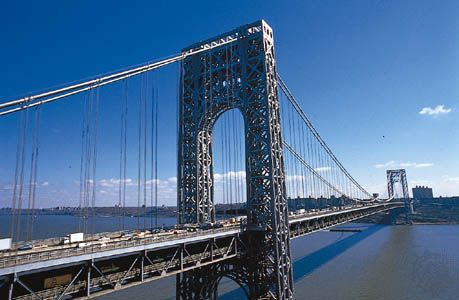
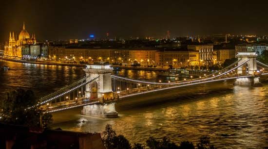
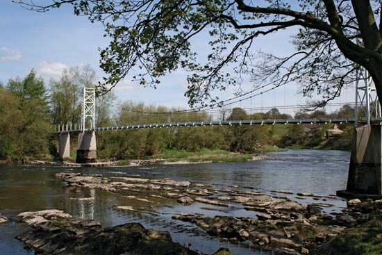
suspension bridge, bridge with overhead cables supporting its roadway. Modern suspension bridges are light and aesthetically pleasing and can span longer distances than any other bridge form. They are also among the most expensive bridges to construct. Though suspension bridges can be made strong enough to support freight trains, they have nearly all been designed for automobile traffic.
Form and mechanics
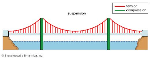
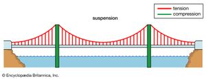
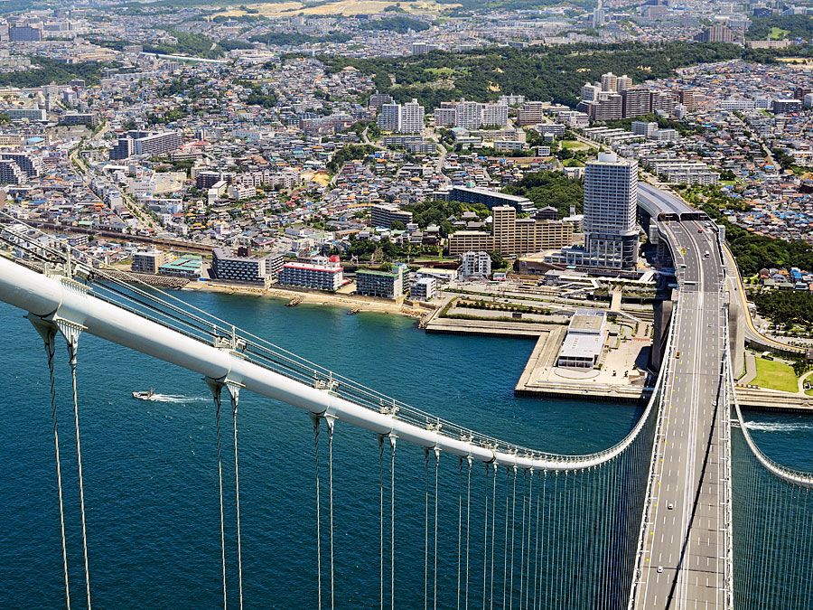
A suspension bridge carries vertical loads through curved cables in tension. These loads are transferred both to the towers, which carry them by vertical compression to the ground, and to the anchorages, which must resist the inward and sometimes vertical pull of the cables. The suspension bridge can be viewed as an upside-down arch in tension with only the towers in compression. Because the deck is hung in the air, care must be taken to ensure that it does not move excessively under loading. The deck therefore must be either heavy or stiff or both.
Since the early 20th century, deflection theory has been used in the design of suspension bridges to calculate how the horizontal deck and curved cables work together to carry loads. First published in 1888 by the Austrian academic Josef Melan, deflection theory explains how deck and cables deflect together under gravity loads, so that, as spans become longer and the suspended structure heavier, the required stiffness of the deck actually decreases. Deflection theory especially influenced design in the 1930s, as engineers attempted to reduce the ratio of girder depth to span length in order to achieve a lighter, more graceful appearance without compromising safety.
Construction
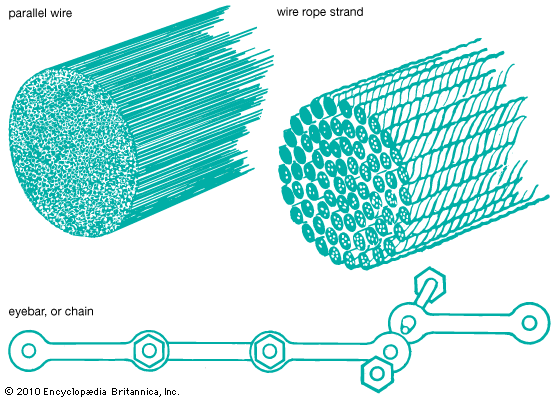
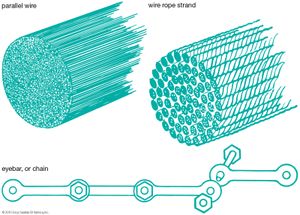
When bridges requiring piers are built over a body of water, foundations are made by sinking caissons into the riverbed and filling them with concrete. Caissons are large boxes or cylinders that have been made from wood, metal, or concrete. In the case of suspension bridges, towers are built atop the caissons. The early suspension-bridge towers were stone, but now they are either steel or concrete. Next, the anchorages are built on both ends, usually of reinforced concrete with embedded steel eyebars to which the cables will be fastened. An eyebar is a length of metal with a hole (or “eye”) at the ends. Cables for some of the first suspension bridges were made of linked wrought-iron eyebars; now, however, cables are generally made of thousands of steel wires spun together at the construction site. Spinning is done by rope pulleys that carry each wire across the top of the towers to the opposite anchorage and back. The wires are then bundled and covered to prevent corrosion. When the cables are complete, suspenders are hung, and finally the deck is erected—usually by floating deck sections out on ships, hoisting them with cranes, and securing them to the suspenders.
History and uses
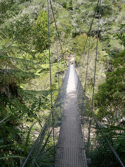
One of the oldest of engineering forms, suspension bridges were constructed by primitive peoples using vines for cables and mounting the road- or walkway directly on the cables. A much stronger type was introduced in India about the 4th century ce that used cables of plaited bamboo and later of iron chain, with the roadway suspended.
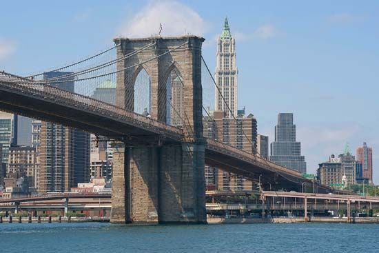
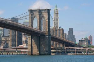
In modern times, the suspension bridge provided an economical solution to the problem of long spans over navigable streams or at other sites where it is difficult to found piers in the stream. British, French, American, and other engineers of the late 18th and early 19th centuries encountered serious problems of stability and strength against wind forces and heavy loads; failures resulted from storms, heavy snows, and droves of cattle. Credit for solving the problem belongs principally to John Augustus Roebling, a German-born American engineer who added a web truss to either side of his roadways and produced a structure so rigid that he successfully bridged the Niagara Gorge at Niagara Falls, New York, the Ohio River at Cincinnati, and, finally, in his masterpiece, the Brooklyn Bridge spanning the East River between Brooklyn and Manhattan at New York City.
The technique of cable spinning for suspension bridges was invented by the French engineer Louis Vicat, a contemporary of Roebling. Vicat’s method employed a traveling wheel to carry the continuous cable strand from the anchorage on one side up over the tower, down on a predetermined sag (catenary) to the midpoint of the bridge, up and over the tower on the farther side to the farther anchorage, where a crew received the wheel, anchored the strand, and returned the wheel, laying a fresh strand. From these successive parallel strands a cable was built up.
Another major development in the modern suspension bridge was the pneumatic caisson, which permitted pier foundation at great depths. It was used initially by French, British, and American engineers, including Washington Roebling, who completed his father’s Brooklyn Bridge.
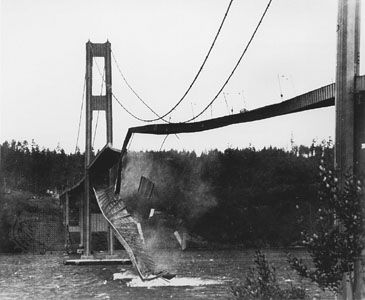
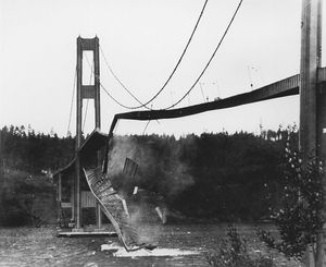
For a time in the 1930s, American engineers experimented with a narrow solid girder in place of the web truss to stiffen the roadway, but the failure of the Tacoma Narrows Bridge in 1940 under aerodynamic forces instigated a return to the web truss. Later aerodynamically stable box girders replaced the web truss.
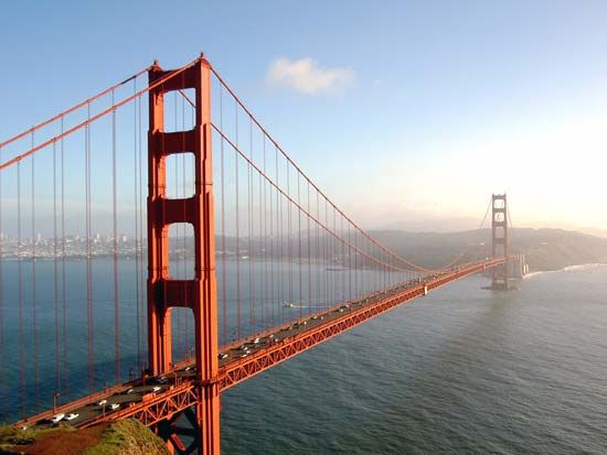
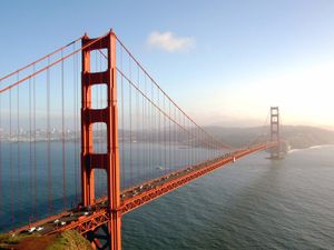
A cable-braced bridge was developed by German engineers at Cologne, Düsseldorf, and elsewhere in the 1950s and ’60s; in this form a single tower at the midpoint supports the roadway by means of a number of cables. Another development of the 1960s, aimed at reducing time of construction, was cable fabricated in the shop. By the late 1980s, three suspension bridges (the Golden Gate, in San Francisco, the Verrazano-Narrows, in New York City, and the Humber Bridge, near Hull, England) had main-span lengths of more than 1,200 metres (4,000 feet).
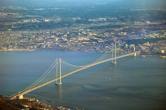
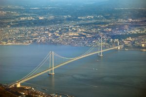
Modern steel alloys are capable of much greater spans, and, since the late 20th century, a number of record-breaking suspension bridges have been built in Asia. The longest is the Akashi Strait Bridge (1998), which spans 1,991 metres (6,530 feet) between the islands Honshu and Shikoku in Japan. In 2019 China completed the second and third longest suspension bridges in the world: the Yangsigang Yangtze River Bridge, spanning 1,700 metres (5,577 feet) in Wuhan (Hubei), and the Nansha Bridge, spanning 1,688 metres (5,538 feet) in Dongguan (Guangdong).

